
Defining Mating Features in an Assembly Drawing
KYT
Use an assembly view to show how a machined part connects to the surrounding hardware. Identify the features that locate it, the clearances it needs and the mating information required to confirm the fit.
Identify the mating components
Include the part number and revision of each adjoining component. Show which items the supplier must make, which hardware is included in the order and which components you will supply.
If an existing component sets the fit, provide its drawing or identify the sample to be used during review. Explain whether the sample establishes the acceptance requirements or only illustrates the assembly arrangement. Any requirement taken from a sample should be recorded in the agreed drawing package.
Show what locates and what fastens
Identify the faces, holes, shoulders or diameters that establish position in the assembly. Use the reference scheme defined in your drawing to locate the related features.
Mark the role of each feature: locating, fastening, clearance, or a combination of these. State which feature relationships must be inspected, and provide the required values and acceptance criteria. Include an assembly section where an internal fit is difficult to see in the external views.
Define each threaded connection
Give the thread designation, direction, usable threaded length and required engagement. Identify the mating item at each connection and show any shoulder, seal or contact face that affects how the parts meet.
For a component with several ports, label the connections separately. The dishwasher tee fitting reference illustrates why the drawing package needs to identify the hardware connected at each port. Thread and sealing requirements must be stated for the particular assembly being ordered.
Check openings and assembly access
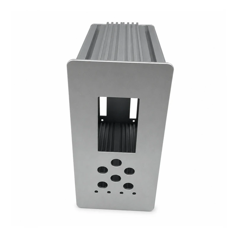
For an enclosure, provide the drawings or installation envelopes of the display, switches and connectors. Locate their openings from the panel references and show the space needed to insert, connect and secure them.
The measurement and control housing reference has a front opening and several round holes. For a similar enclosure, identify the installed hardware that controls each opening, together with any labels or markings that must align with it. Include the internal assembly outline and access needed for wiring or service.
Specify matched sets or interchangeable parts
State whether parts are accepted as matched sets or must interchange with other parts made to the same drawings. Confirm the mating specification and acceptance method before production.
For a cover-and-barrel project, include both drawings and the closure features that control fit. The EKL4 battery cover reference and battery barrel reference show the types of items to identify. Specify the required mating dimensions, drawing revisions and how sets or individual parts should be identified and packed.
Review changes against the complete assembly
When a connector, board, fastener or mating part changes, identify the affected drawings. Confirm the revised openings, locating features and access requirements before issuing the next package.
Before sending the drawing, check that:
- Every mating component is identified by part number and revision.
- Locating, fastening and clearance features have the information needed for review.
- Threads, seals and contact areas are defined where required.
- The required inspection and assembly acceptance method is stated.
- Supply scope, quantities and matched-set requirements are clear.
Send the assembly drawings with the current part models and any interfaces that remain open for discussion.